Showing posts with label project. Show all posts

Friday, June 27, 2014

Collecting vs. Making water on Luckness

For people who follow my blog closely, you'll remember that my water maker stopped working while I was in the Marquesas, several months ago.  At the time, I converted the water maker to manual operation and was spending roughly an hour a day, manually pumping the water maker to create just over a gallon of water.  It started to get tedious pretty quickly.  But I'm not afraid of doing tedious things and I was making water ever day this way.

On the passage from Nuka Hiva to Fatu Hiva, an upwind bash, I tried to make water.  I quickly realized how difficult that would be.  You need to put quite a lot of force into the pump to operate it and doing so in a boat which is pitching and rolling in a seaway was difficult.  Its hard to push down with any force when the whole boat is flying upward as it does when climbing the face of a wave, before crashing down on the other side.  Downwind passages are more peaceful, although again making water manually would be very tedious.

Around this time, a friend of mine, Dave Mancini, who is cruising s/v Swan around Mexico at the moment, forwarded some information about how he and his wife Rhonda dealt with water as they cruised through the South Pacific on their earlier passage.  Swan is a Pacific Seacraft 34, so very similar to Luckness.  Swan doesn't have a water maker and relied on collecting rainwater on their entire journey.  They went through French Polynesia, Tonga, Fiji and then up to the Marshall Islands and back to Washington state.  Dave seems to pass along all sorts of good info every time I see him or exchange email with him.

In the past whenever I thought about collecting water on a sailboat I would think about it in terms of some sort of canvas collection system I would sew together, incorporating a hose of some sort which would lead to a jerry jug.  Or perhaps some sort of canvas I could add to the mainsail to collect the water the sail captures.  These techniques seemed complicated.

Dave's technique is simply to plug the scuppers on both side decks on his boat.  Once you do this, the entire boat becomes your water collection surface and as the water drips off everything it finds its way to the side decks where it collects.  He then puts a rag over a funnel, places it into a jerry jug, and uses a tupperware bin to scoop water from the side deck into the funnel.  Finally he adds 1/2 teaspoon of bleach to the jug before adding it to his water tank.

I've tried this technique now, several times.  Its super easy and can capture a lot of water.  Since hearing about this from Dave I've started to hear other cruisers talk about it as well - when it rains I've heard others talk about going to plug their scuppers to collect water.  However I've also mentioned this technique now to several people who have boats where this would work, and they didn't know about it and liked the idea.

So.  If you have a sailboat, and your sailboat has high bulwarks, and the scuppers in your side decks are easily plugged, this technique can work for you.

Dave uses four rags to plug the scuppers, as their are two holes on each side.  First let the rain fall for a little while to clean any salt off the surfaces.  I go around when this is happening and use a rag to wash away any dirt I can.  Let it rain long enough so that the water pouring down the scuppers is clean.  Then plug the scuppers and let some water collect.  Put a rag over a funnel, put it into a jerry jug, and pour water into the funnel.  The rag is a good idea as I constantly find little bits of dirt and hairs in the rag after pouring clean water through it.

Plug the scuppers with rags, once the water is clean
Let the water collect...
Prepare the funnel, rag filter and jug
Scoop water, pour into jug, repeat
I didn't have any real rain while I was in the Marquesas.  When I first got to the Tuamotus it rained heavily the first day I was there.  I thought I would try plugging the scuppers just for fun, to see what would happen.  Both of the side decks were full of water within 1/2 an hour.  I wasn't prepared yet to filter it and use it for drinking water - but I was able to have a fresh water bath after my passage, soap on one side rinse on the other.  I then drained both side decks, plugged them again and started rinsing salt out of towels and clothes.  I was sold on this technique.

My water maker, when it was working, only made 1 1/2 gallons of water an hour.  It used between 6 and 8 amps to do this, so power was a concern on cloudy days (I prefer not to run my engine to charge my batteries.)  With so little water available I would never consider having showers or washing my clothes onboard.  This all changes when water becomes plentiful, as it does with this technique - at least in areas with rain.

Back to the Tuamotus and my first experiences.  A few days after my first experiment some more squalls started to roll through.  I started hoping that the passing squalls would hit me directly rather than wishing that they would miss as I did in the past.  I wanted to collect the squall water!  I had two close misses that day and was able to collect 5 gallons of water which I treated with bleach (1/2 a teaspoon) and poured into my tank.

Since then I have had several occasions when I have had heavy rain.  One day while I was in Papeete I collected 15 gallons for my water tank and it continued to rain.  I then started washing clothes.  I would collect 5 gallons, use it in my double sinks to first wash clothes and then start rinsing.  Rinsing takes a lot of water so I went out to pour 5 more gallons into the jug, using 10 gallons to wash my clothes.  On days when its raining hard, or lightly but constantly, you'll have more water than you'll be able to use.  I filled my water tank, washed clothes, washed myself and then unplugged the scuppers to let both side decks drain as they were completely full, with water overflowing over the top of the cap rails.

Collecting rainwater is awesome!  I haven't made water with my water maker in the last two months. Between collecting water and getting water from shore when its available, my tanks are always full.  Thanks to Dave for passing along his advice on how he did it on Swan.  Any other owners of PSC 34/37 or other boats with high bulwarks - take note, this may apply to you as well.


Tuesday, September 3, 2013

Thoughts on my auto pilot

Ok, there may be a few more boat project posts before I depart...

I did a little work modifying my autopilot a few months ago but was hesitant to post details.  I've basically violated its warranty and made it a little weaker in order to achieve a tighter turning radius for the boat.  This was a tradeoff that I wasn't even aware I was making back when I had the autopilot installed.

A little background.  If you're considering buying an autopilot for your wheel steered boat (tillers are a whole different thing), you should be aware that Raymarine, Simrad and possibly other manufacturers, limit the angle the rudder is able to deflect to each side to around 35 degrees.  In talking with the Raymarine folks, they felt that if the rudder deflected much more than 35 degrees that the forces that could be imposed on the rudder could overwhelm the autopilot and reduce its lifespan.  So, they require that when you install the autopilot on the boat that you restrict the maximum rudder deflection to each side to 35 degrees.

I believe my Pacific Seacraft originally had a 55 degree maximum rudder deflection - so when the autopilot was added, I lost 20 degrees of rudder travel to each side.  This is almost a 40% loss of rudder deflection.  This means that the turns I used to be able to make were tighter than they were after installing the autopilot.  This doesn't matter when you are out in open water sailing around.  But when in close quarters maneuvering the boat to dock or move around a marina - being able to turn tightly is nice.

After realizing this limitation I started thinking about how I could compromise the system to achieve a tighter turning radius.  Basically, if you end up with something that allows the rudder to deflect more than 35 degrees, you violate the warranty.  In the end, I decided that I wanted to be able to maneuver the boat more easily and have modified my setup.

A few pictures to clarify how this all works.

The autopilot computer controls a linear drive which can push or pull a rod attached to a tiller arm which is attached to my rudder post.  This is how the autopilot turns the rudder.


The bronze arm is the tiller, the autopilot arm on the left is attached to the tiller and the tiller is attached to the rudder post.  At the top of the rudder post is the quadrant, which is how the steering cables attach to the rudder.


The steering cables wrap around the quadrant, so as  you turn the wheel you pull on the cables which rotate the quadrant and the rudder turns.  But clearly you don't want to be able to turn the rudder around until it hits the hull, so manufacturers build a support bar which crosses above the quadrant, and then there is a post on the forward part of the quadrant.  As the quadrant rotates, the post (seen with a short hose chafe sleeve above) will hit the bar and stop the wheel from turning the rudder any further.

Originally there were no pieces of wood on the support bar, which would give the maximum deflection of the rudder - it could rotate on one side until the center post hit one side of the support bar, and then rotate to the other side until the center post hit the other side.

Without the pieces of wood in the above picture, you can get 55 degrees of travel in each direction.

After my autopilot was installed, there were two pieces of starboard where the wood is now.  The starboard stops were 1 3/4" wide, which limited the travel to around 39 degrees to each side.

My modification was twofold.  I moved the attachment point of the autopilot from being 10" out along the tiller to 8".  This gave a larger deflection for a given amount of travel of the autopilot rod.  The Simrad unit uses the same tiller arm and attaches at 8" so the tiller arm is strong enough to accommodate this new attachment point.  I then found the maximum limits of travel for the autopilot and created the wood stops to have the rudder stop travel before pulling or pushing the autopilot rod out of/into the linear drive stops.

I ended up with the two pieces of wood being different sizes and my rudder now travels out to 50 degrees when turning to port and to 43 degrees when turning to starboard.  I gained a little to starboard and 11 degrees to port, roughly a 30% improvement to port.  The boat doesn't turn as well to port as starboard, as to starboard you can use prop walk in reverse to tighten a turn, this doesn't work to port.


After realizing the limits my autopilot imposed on me and going through this process, I started to think about my choice of autopilot.  There are different autopilots made which are mounted above deck and which drive the wheel directly.  These autopilots may not be as elegant, but they wouldn't impose any limit on the rudder travel.  See the CPT autopilot for example.   I would be tempted to go something like this route if I was to do it all over...

Monday, September 2, 2013

Garbage can

Oops.  I thought there would be no more project posts.  One last little one...

This is one of the simplest boat projects ever.  Other Pacific Seacraft 37 (and maybe 34?) owners may appreciate this.

The garbage can in my galley came with the boat when I bought her.  I suspect its over 20 years old.  There was some duct tape on the bottom holding a crack together, and some more on the side.  There were more cracks on the side and toward the top which were getting worse.  The garbage can was leaking and falling apart.  So I needed a new garbage can.

I pulled the can out, and looked for identifying marks.  It was made by rubbermaid, and there were the numbers 2957 on the bottom.  If you google 'rubbermaid 2957' you'll get a lot of hits.  Its pretty cool that the same garbage can has been made for so long, I thought I would be out of luck buying a new one.


Home depot sells this garbage can and you can verify online to make sure your local store sells them.  It cost me a little less than $10.  So if you happen to have an old, cracked garbage can in your PSC 37, head on over to home depot and pick up a new one.  It will have four tabs you need to cut off.  As you need to modify the garbage can you buy, I'm claiming that it qualifies as a boat project - one of the simplest ones.


Last project post prior to departure....got a lot done!

I plan to leave Seattle for my next cruise in early September, perhaps around the 12th or so, maybe sooner, maybe later.  More on that later - hopefully my next blog post will be about my starting to move with a few details about my plans over the next few years.  Without giving too much away - think endless summer, blue warm waters, topical paradise's and interesting destinations.  Its sooo close at this point, but not quite there.

In the mean time, over the past six weeks I've been busy on all sorts of projects.  Some of these things probably deserve their own separate post but I'm going to glom everything together into one massive post - the mother of all blog posts.

I don't really expect anybody to read all of this.  Here are some of the things I've been working on...

Small things first:
  • Following up on my post detailing how my new locker gaskets were formed, I've also sealed the cockpit engine access on the cockpit sole.  There was a small leak in one corner of this hatch.  Fixed now.
  • I've written about how I've made it easier to remove the stove from my galley by carving little indentations in the teak surround.  This has been useful, as I had one last project to do on the stove.  After I replaced the stove gimbal pivots I discovered that the aft stove gimbal pivot lock was in the wrong spot.  There is a way of locking the stove from rocking back and forth which involves sliding a short rod into a hole in the surrounding enclosure.  Well, the hole in the aft enclosure face was in the wrong spot.  So I marked the new spot, removed the stove, made some measurements, replaced the stove, tested the spot, removed the stove, started drilling the hole, replaced the stove, tested the hole, removed the stove, adjusted the hole, replaced the stove, tested the hole, removed the stove, marked the hole, epoxied the hole, replaced the stove, tested, removed the stove, finalized the spot by adding a metal cover and sanding the epoxy, replaced the stove.  I'm pretty happy that the stove is easy to remove and install now.  The stove now locks solidly in place.  See how tedious boat projects can be...if you're really attentive to every little detail?
  • Bought passage charts for my known coming voyages.  These are charts which cover a very wide area.  One chart covers the west coast of America down to San Diego.  Another covers San Diego to Mexico and part of the South Pacific.  I had some similar charts for my trip to Hawaii and back to Seattle.   I found them useful - as I would update them daily just to prove to myself that I was actually making progress.  On longer passages its nice to have a way to track progress.  It was pretty exciting looking over my new charts and looking at my upcoming voyaging areas!
  • Created two amsteel pendants to lower the attachment point for my lazy jacks from the bow shackle at the mast where my running backs attach.  The lazy jacks were chafing my running backs as I ran them up and down.  This is now solved.  I realize this is hard to visualize.  Just think of it as yet another problem that was fixed.
  • Created new fitted sheets.  I spent some time visiting family on Vancouver Island and Vancouver.  While on Vancouver Island visiting my Mother I had her teach me how to create fitted sheets for my forward berth.  New top and bottom sheets.  They're awesome.  This sewing stuff isn't so hard.
  • Started to clean and lube my winches.  At this point I've done four of six and have found one broken spring.  The two on the mast will be finished tomorrow.
Some of the larger projects, most with pictures, follow:

Installed a new fridge:

My old fridge was a alder/barbour cold machine, one of the original DC fridges using the then new danfoss compressor.  The fridge was working - but I suspect that it was 20 years old and I just did not trust it anymore.  I wanted to do a little preventative work now to try to avoid it breaking down over the next few years.  On the one hand, changing a working system introduces the potential for the new system breaking instead...but I felt that I should do this.

I bought a frigoboat capri 35 with a Merlin smart speed controller and a Guardian thermostat.  The thermostat is digital, and is therefore much more accurate than what I used to have.  The new system should be much more efficient.  

The merlin smart speed controller is cool - it keeps track of how often the fridge comes on, and for how long, and optimizes the speed at which the compressor runs.  It turns out that to be most efficient, the compressor should be run for as long as possible - which means at a low a speed as possible.  My old fridge had a single speed (high) where it would draw 6 amps - my new fridge has 6 speeds it can run at and the most efficient (slowest) speed only draws 2.1 amps.  The speed controller will adjust the speed to try to achieve a run time of 20 minutes an hour which is can do in Seattle by running at the slowest speed for 8 minutes and then being off for 20 at which point the fridge box has risen from 40deg to 42 and the thermostat turns the cycle on again.  The guardian thermostat is accurate - it allows me to set the set point for the fridge and how many degrees it can rise before turning on.  

In the tropics I'll monitor my power usage and may need to raise the temperature of the fridge from its current set point of 40 - on my last trip I had the temperature quite a lot higher which was fine for the types of food I kept in there.

This project was fairly straight forward, just installing hardware I bought.

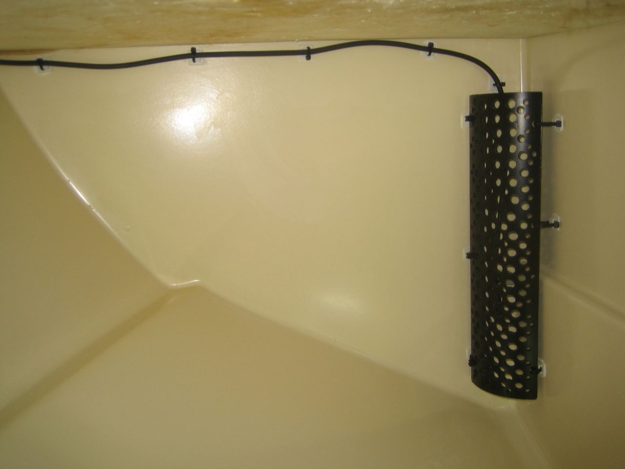
Installing thermostat wire high in fridge box
A little cage surrounding the thermostat
The thermostat needed to be installed on a wall of the fridge box where the evaporator wasn't.  I choose a back wall.  However I tended to pile food up in the fridge and I didn't want food to be piled up against the thermostat.  So I ended up buying a 4" PVC pipe, quartering it and drilling a bazillion holes to aid airflow.  I'll find out if this ends up being effective - if not, I'll relocate it later...
The guardian thermostat panel
Aft water tank:

This is the second time I've had to work on my aft water tank.  The last time I worked on it, I was hoping never to see the insides of this tank again.  The last time I worked on the tank it was due to their being a leak - I fixed that.  As part of that project, I decided to finish the tank liner with an epoxy in order to seal the tank better.  I don't recall spending too long on surface preparation for the epoxy step - I spent quite a lot of time fixing the leak and then gel coating the fiberglass I used - but the preparation for the final epoxy step was a little light.  I used to think of all epoxy's as some sort of magic glue which would stick to anything.  It turns out this was wrong.

When I got back from my last cruise I inspected my water tank carefully and noticed a small bubble in the epoxy which after a little prodding turned out to be a massive delamination of the epoxy from the tank interior.

Its a little hard to see from the picture, but there is a large piece of epoxy sitting on top of the divider between the aft and forward sections of the tank.  Once I had pulled some epoxy out, I could pull sheets of it off.  I briefly considered turning this into a storage area to avoid all the work on fixing the tank to make it potable water safe again, but decided to return it to use as a water tank.

Getting the lid off is a chore.

Lid removal tools
Cut and pry the bar into a gap you create, then pound the bar down between the lid and tank
Use wedges to create gaps, and pound them around the tank lid
Once the lid is off, you will have a lot of silicone to clean up.  Its not a lot of fun.

Once it was cleaned up, I needed to remove the old epoxy liner from the tank.  This should have been pretty much impossible as the epoxy should have bonded to the tank in such a way that it needed to be ground off - but by applying a lot of pressure with sharpened putty knives I was able to scrape all of the epoxy off.  I also scraped some of the gelcoat off, notice the pitting in the photo below.  This took about three days of hot sweaty work - balancing like a tripod while pressing carefully and hard on the sharp putty knife to have the epoxy flake off and shoot in all directions.  I had the whole area tented off with plastic - no photos of that, sorry.

Gelcoat pitting after removal of old epoxy liner
At this point I don't really want anybody to follow how I approached the repair and lining of the tank - its hard to get definitive answers to how to finish a potable water tank.  Companies tend to shy away from this area, as government regulations require that if a company declares a product safe for some use - they need to prove it for a particular tank size, construction and process.  Nobody is interested in certifying their product safe for water tanks on small sailboat fiberglass water tanks.

So after a lot of reading, I decided on using an epoxy liner - but with a much better epoxy than I used last time and also much better preparation to the surface.  The epoxy is a 100% solids epoxy.  I think it will be ok...

I first needed to repair the damage to the gelcoat I had inflicted with my putty knives removing the failed epoxy.  I used an Adtech product, P-17 white with a black hardener, a high head resistant rigid polyester filler.  This is an epoxy as well - combine filler and hardener, mix and apply to tank before it hardens.  I applied a good solid coat to the entire tank and then sanded with 80 grit all around to create a good surface to epoxy to.  

The epoxy I used was Fiberlay Pro Glas 1200 UV epoxy resin and the fast hardener.  Do your own research and pick your own route if you need to pursue this type of project...

The final piece of this puzzle is what type of silicone sealant to use to seal the tank.  I used the 3M marine silicone last time but have discovered that it contains chemicals that may not be good to have in a potable water tank.  I couldn't find a source for a food safe silicone, so after reading, discovered that aquarium silicone sealants are good for water, as they are used to seal tanks which have fish swimming in them, and tropical fish are very sensitive to chemicals.  So that's what I bought, through amazon.  A little later I was in Tacoma Screw here in Ballard and saw they have their own branded silicone sealant which is NSF 51 food safe - that would have been a good choice.

I replaced the lid to the water tank yesterday, sealed it and will wait 7 days for the silicone to fully cure.

Bomar deck hatches:

I noticed some delamination between the silicone seals in my deck hatches and the polycarbonate lenses.  I didn't want these to leak and my buddies at Yacht Fitters have gotten good and fixing these hatches and they passed along some advice on how to proceed.  I removed the hatches, popped the lenses out and cleaned everything up.  I then saw a little corrosion on the hatch frames and thought I would just spray paint a patch as I wasn't too concerned with the appearance.  So I sanded away the corrosion, bought a zinc spray paint primer, applied it, and then added two coats of spray paint.  To cut the story short, the spray paint failed badly and I ended up sending the frames to Seattle Powder Coat, which did a fantastic job.  Clear cut plastics in Fremont cut new frames for me.  Yacht Fitters fit the frames into the hatches with my helping out.

The sealant used was Dow Corning 795, which is used in glazing.  

Looking out my new hatch!
The new hatches are really nice.  I can see through them again!

Halyards:

By the end of my last cruise, I discovered that my jib halyard had chafed badly.  The chafe happened just as the halyard entered my halyard restrainer.
My old jib halyard,  at the top of the splice at the sail attachment end
I've heard about riggers adding dyneema chafe guards to halyards from a few sources.  Luke at Yacht Fitters does this, and I had him build two new halyards for me - I thought I would have a new main halyard made with a chafe guard as well.  The results are really nice - I recommend Yacht Fitters for this work if you're in the area.
My new main halyard on left, my old-old main halyard which has become my trysail halyard
The new halyards are core dependent - a dyneema core with a polyester cover.  Luke removes part of the cover, splices on the dyneema chafe sleeve and then performs the eye splice in a manner which I don't really understand but which ends up being much nicer than the Samson splice they present in their splicing manual.  

Also halyard related, I added a little more organization to my mast by adding line holders to hold my lines up:
Hooks to hold halyards at the mast
Furler and halyard restrainer:

My original jib furler was as old as the boat, 22+ years.  It was another piece of gear I was losing trust in.  Getting new parts would be difficult, and there are better designs out now.  I bought a Schaefer 2100 furler, Luke came by and installed it one day.  I helped out, it was pretty interesting seeing how a furler is installed, while the mast is up.

Schaefer 2100 furler
The furler came with a new halyard restrainer which was much better than the model I already had on the mast - so I went up and drilled the old restrainer out and drilled and tapped the new restrainer in.  

The schaefer restrainer is much nicer.  I suspect that if I had the new restrainer that I wouldn't have had the jib chafe I experienced last time.  With the jib halyard having a dyneema chafe sleeve and a new restrainer at the old problem location, I think that problem should be fixed.  I'll find out...

The schaefer furler manual suggests that the top of the upper swivel be less than 6 inches away from foil top cap.  Originally the distance was 12 inches, so I constructed a circular strop made from 1/4" amsteel.  The strop worked out really well.  With the strop installed, the top of the swivel is just under 6" away from the end cap.

Sail head to strop to swivel to halyard to restrainer to sheave's and down.
Reef lines:

While I was out on my last cruise, I also noticed that my reef lines were chafing in the region of the aft boom end cap.  There are sheaves in this region, with aluminum plates separating the sheaves from each other - the plates rise above the sheaves, and the reef lines were chafing on the plates.  I ground the plates down to be smaller, which will help with the problem.  I also installed dyneema chafe sleeves in the region of the chafe - I did this work after a few hints and some instruction from Luke at Yacht Fitters.  The chafe sleeve goes on pretty easily.  I placed one of the sleeves in the wrong spot and was able to cut the whippings, remove the sleeve bury's, move the sleeve to where it needed to be and install it again without any damage to the reef lines.  Nice!

I discovered after adding the chafe sleeve to the reef lines that they no longer fit out of the boom end cap - the diameter of the line increased enough that they would not exit cleanly.  So I ground down the end cap to accommodate - no big deal.

I decided to buy new reef lines before adding the chafe sleeve - one of the lines was chafed badly enough it needed to be replaced anyway, and the second line was ok, but I wanted to keep them both in sync and so bought two new lines.


There are a few things going on in the picture above.  I have a new topping lift - I had used amsteel for the line which exits the boom, goes up to the pulley and back down to the boom cap.  Amsteel is slippery and I found it tedious to cleat it off - I needed to have a lot of wraps around the cleat or it would slip - its pretty surprising.  I had some warpspeed on board intended for something that was no longer needed, so I used that for my new topping lift - the polyester cover cleats off much easier.  This was my first core dependent splice - it worked out, I used the Samson recipe.

You can see the chafe guards on the reef lines.  The other new thing I added are two short amsteel lines which attach to the reef lines as they wrap around the boom.  These straps hold the reef lines back toward the end cap.  On the port side of the boom you can see an amsteel line going from the padeye, under the clew strap to the reef line wrap. This is to hold the reef line from moving forward.  I wanted the reef lines to pull back on the new sail clew, not simply pull down.  I found that the wrap around the boom would continually move forward to be under the reef clew rather than remaining further back.  I'll see if holding them in place like this works - it seems simple enough.

Monitor trim line:

On the monitor self steering wind vane, there is a line which is used to adjust the trim of the vane to allow you to make course corrections.  This line is a loop which goes around a large sheave at the monitor and then for Luckness, forward along the starboard side of the cockpit to a SS ring which is under tension by some shockcord.  

The important piece of this is that you pull on the loop of line to adjust the vane direction.  

When I was leaving last time I didn't have a good solution for this line - I used a small diameter dinghy control line and fastened the ends together by stitching and then whipping.  It was a bit of a mess.  The join would enter the sheave and then get tripped up most often popping the line off the sheave.  So I continually had to watch were the join was and adjust it to remain far from the sheave.  Anyway, it was tedious.

The Scanmar Monitor manual talks about this control line being 1/8" dacron, but beyond that, doesn't say anything else.  I couldn't find 1/8" dacron - is it even made anymore?  High tech lines have taken over now.

Once again, I'm using amsteel.  Amsteel is super easy to splice into endless loops, but is a little slippery for this application.  If I find the control line slipping, I've decided that I will add some wax to the equation.

I now have a new 7/64" amsteel trim line.  Here are my old and new trim lines, in the join areas:

New amsteel monitor trim line splice region - slick!
I don't show the bury region of the new splice - I taper the amsteel tails nicely so as you run your fingers along the line you can't feel where the bury happens at all.  I can now pull on the trim line and as the splice enters the sheave nothing happens, the line isn't tripped.  It is now a real endless loop.

This is only a small thing - but during my last cruise I was finding myself, at night, in large wind and waves, leaning over the back of my cockpit holding the monitor sheave while I tried to adjust the old splice to a more favorable area of the line.  I won't miss those moments.

Dorades:

During my last cruise, I found that while I was on the same tack (either) for a long time while getting water over the deck, that my port side dorade would leak.  The water was entering the headliner under the dorade, leaking into a light which is mounted there, filling it up and shorting it out.  It got to the point where the on/off switch was inoperable due to corrosion and the light was dimly staying on all of the time.  I adjusted something in Hawaii but the dorade leaked again on my trip to Seattle.

I recently took the dorade apart again.

The port side dorade
The dorade box surrounds a mushroom vent which can be closed.  I thought the mushroom vent was the problem, that water was intruding between the top of the vent and where it was meant to seal.  I took the vent off and while doing so discovered that there was no sealant between the vent base and the cabin top in a few areas - and that there were rust streaks under the vent base over to the vent hole - showing the path the saltwater was taking.  I cleaned everything up, sealed the vent well and this problem should be fixed.  Then I did it for the starboard dorade - it wasn't leaking but it ended up having the same lack-of-sealant problem, so I'm happy I fixed it.

Teak vent in hanging lockers:

My two hanging lockers continually have a mildew problem, mostly in the lower region of the locker where the air doesn't circulate due to clothes hanging above.  I think a way of helping the mildew problem will be to allow air to circulate - so I've just cut two holes in this region of the lockers and will install teak vents.

Holes ready for their vents
Teak shelf in navigation station locker:

There is a small locker beneath the nav station which was designed as a hanging locker.  I use it for footwear, but this only occupies 1/2 of the locker - the upper region was unused. 


I installed a shelf in this locker.  After measuring and cutting some teak grating, I mocked up the shelf and then epoxied four hardwood tabs into the walls of the locker.  Once the tabs were in place, I continued building the shelf, applied teak oil and have installed it.  The shelf is removable, but fits snugly when installed.  I'm not sure how I'll use this space - possibly food storage, but its now a large handy area to store something.

The four hardwood tabs to support the shelf
Note vertical tab on left of picture in front of grate to hold shelf in place
Conclusion:

I think of my last cruise as a year long sea trial.  I came back with a big list of things I wanted to improve on Luckness before heading out on a longer cruise.  I think I've pretty well gone through the list now - there are a few things left, but they will either be done before leaving or early in my next trip.


Tuesday, July 16, 2013

New cockpit locker gaskets

Here's another project post I have been meaning to post for a little while.

---

Before leaving on my last cruise I wasn't happy with the gaskets I had in all of my cockpit lockers.  There are port and starboard aft cockpit lockers, a propane locker, a lazarete and the cockpit sole which comes out to give engine access.  There were gaskets on all of the lockers and the sole which were old and leaking.  I searched through McMaster-Carr for good gasket material and found what I thought were a few promising pieces.  So I bought a bunch of gasket material and installed it on all the lockers.

Unfortunately, I found that the gaps between the different areas of the locker lids and the locker were not uniform.  So I bought some thinner gasket material and tried to blend it in to the thicker material I already had.  I tried a couple of times to get a decent seal and finally ran out of time without a good solution.
Starboard aft cockpit locker lid.
In the first picture above, note that the thicker gasket material on the outside (right) isn't really thick enough to seal well on the outside of the locker while the thinner material on the left is too thick in parts.
Thick and thin gasket material with obvious gap where they meet...
Even the thin gasket was too thick in parts
I left on my last cruise with the lockers sufficiently sealed to keep out rain but I was unsure how much of a problem the gaskets would be out on the open ocean.   It turns out that it is a minor problem - you end up with lots of waves which find their way onboard and once onboard the water finds its way into the lockers.  It wasn't a huge problem - the extra water leaking in wasn't going to sink me, but all of the lockers leaked.  The engine and transmission are below the cockpit sole gaskets and leaking saltwater isn't good there (although I kept on top of this, no damage was done.)  The propane locker also has mechanical and electrical bits which do not like salt water (all replaced recently,) the fridge is in the lazarette and I don't want that to have salt water dripping on it, and in general all of the lockers have bits and pieces which I would like to keep isolated from salt water as much as possible.

So, I wanted to find a better solution before leaving this time.

Once I understood that the thickness of the gasket material had a very wide range in the different areas of the locker lid, I realized that I wouldn't be able to find a material that would work well.  After a while I decided to try to form my own gaskets out of something - I settled on Sikaflex 291.  Sikaflex is a medium strength adhesive sealant, and when cured is slightly flexible.  I thought it would adhere well to the locker lid and hoped that it would be tough enough to withstand some abuse as the locker lids were opened, closed, stepped on, etc.  There are probably other sealants which would work just as well.  Sikaflex is slightly less expensive than 3M 4000UV which would also work well I think.

Once I had decided on the gasket material I had to experiment a little to find an approach that worked.  I tried three times to form the gaskets in the lockers - the third time worked pretty well.  If you're interested in doing something like this yourselves, this might save you some time.

The general approach is to clean the locker lid well so the sealant will adhere, apply a lot of the sealant in the right spots on the lid, find some way to isolate the sealant so that when you close the locker lid with the sealant still uncured that it won't stick everywhere and seal the locker lid permanently closed, and then allow easy cleanup, leaving the gasket you've just formed.

After several trials, I found an easy way to figure out where the sealant needs to go and how thick it should be.  The problem is that unless you have a small volunteer who is willing to climb inside the locker while you close the lid on them and have them trace the inside of the locker lip on the lid, its not always obvious where the locker lip meets the lid.  I have some modeling clay onboard - but silly putty or some other clay-like material would work here.  Form a thick tube, put a strip of blue tape down on the locker lid in the area you think the lip will hit, put the clay there and then a small piece of wax paper on top of the clay and close the locker lid.  Open the lid and see how the lip impacted the clay.  Make a couple of marks on the lid to indicate where the lip is at that spot and make a mental note of how thick the gasket should be at that point.  Move the tape over slightly, reform the clay into a tube, and repeat until you have a whole series of dots indicating where the locker lip hits the lid.  Then connect the dots.
Modeling clay ready for the locker lid to be closed.  Mark the impact region
Connect the dots
Ready for the sealant
You probably want to buy a number of the tubes of sealant, and practicing on a locker might be a good idea as well.  I did!

Now simply go around with the sealant and apply a thick bead in the lines you found - the sealant is going to be the gasket, so make it thick enough to form a good seal between the locker and the lid.  This is where its useful to have made notes on how thick the clay tube was when you closed the lid on it around the locker.  Some areas are paper thin, others are quite thick.


You want to apply a wide enough bead so that when the gasket forms, there is extra sealant on each side of the locker lip - I wanted the gasket to not just form on top of the lip, but seal its edges slightly as well.  So use lots of sealant.

At this point, you have the problem of how do you close the locker lid with the fresh sealant on one slide without the sealant sticking to the locker and forever sealing the lid to the locker.  My first attempt was to apply foil to one side - which upon reflection was a really bad idea and which turned out very poorly.  The sealant adhered to the foil very well, making it pretty much impossible to get off.  However on that first attempt I also applied blue tape to the outsides of the lines I formed when connecting the dots - and I found that the sealant did not adhere to the blue tape.  I discovered that I didn't want the sealant to be only inside the lines, so no need for blue tape there - but the fact that Sikaflex didn't adhere to blue tape was useful - cool.

So what I did was take long pieces of blue tape and apply them to the sealant with the top of the blue tape (the non sticky side) facing the sealant.  The blue tape then has its sticky side up, and I applied wax paper to the sticky side of the blue tape so that it wouldn't stick to the locker.  I made the wax paper wide enough to ensure that if any sealant leaked out of the blue tape it wouldn't seal the locker closed.  (I can't stress that part enough - don't seal your lockers closed.  That would be a bummer.)

One piece of blue tape applied, sticky side up
Tape and wax paper applied
Once all the tape and wax paper is applied, I ran my fingers across the wax paper smoothing the sealant out slightly.  Now you have to form the gasket out of the pile of sealant you have.  At this point I would close the locker lid and briefly close the latch securing the lid in place.  Then I would release the latch and not touch the locker lid again for several days.  After three or four days I removed the tape.  The tape came off pretty easily - Sikaflex 291 and 3M blue tape don't seem to stick.  The sealant was still just slightly tacky at that point, I would make a point of opening and closing the locker lids a few times a day just to make sure the tacky sealant didn't adhere to the locker.  After a week or more the sealant is fully cured and you have new gaskets.

Newly formed gaskets
I found that the tape would crease in some spots which you can see in the image above on the left.  These creases may be allowing some water in, allowing leaks to get into the locker.  I'm not sure how to avoid those.  It would be easy enough to apply a small bead of sikaflex in the fold area, then blue tape, wax paper and fill in the gaps.  I might do that.

I completed this project a little over two and a half months ago as I write this.  At this point, the gaskets are still slightly flexible which is how I expect them to remain.  I think this is going to work.  I found that when I spray a hose directly at some areas of the locker a little water will come through, but the lids all have a much better seal than they ever did in the past.  The gaskets that formed are very thin in parts, and gradually get thicker and wider as needed, conforming to the locker lip.

Once again I'm glad that I don't have to pay myself by the hour - these would be expensive gaskets!  However the results I have so far are much better than I was able to achieve by buying pre-made gasket materials.  If I can isolate the leak areas I think I will be able to apply some more Sikaflex to those areas and build up the gasket to cure the leaks.  If the leaks I find are a problem then I'll consider building up some more material.  What I have now is much much better than what I used to have.

Sunday, June 30, 2013

Monitor pendulum lines and amsteel

[Update at end added Sept 27, 2013.]

I'm still working through some project posts that have piled up.

---

Luckness has a Monitor self steering wind vane, made by Scanmar.  Its awesome.  I used the Monitor to steer all of the time offshore and I really liked how it performed.

I won't go into any detail on how it works, other than to say that the Monitor at the back of the boat is connected to the wheel in order to steer the boat.  The connection is through lines which run beside the cockpit and then to the wheel around a hub.  Its a very simple setup and works well.  Most of the parts are very robust and sturdy - the exception being the lines themselves.

In my experience so far, the pendulum lines chafe continually.  My setup is pretty nice.  There is one set of blocks to turn the lines from the cockpit onto the wheel at a right angle, and one set of fairleads that turn the line around a stanchion.  The line seems to run freely at both places.  When I examine the line passing these points I don't see any problem, everything has a lot of clearance and there is very little friction.  However the nature of this steering is that it undergoes continual small adjustments and frequent larger ones.  The lines are just constantly in motion, moving back and forth around all the blocks and fairleads.  What would not be a chafe issue for normal lines run as halyards, sheets, reef lines or just about anything else simply accumulates and slowly chafes the pendulum line.  Its pretty brutal.

On my trip down to California in 2011, on the last night before I pulled into Drakes Bay one of the fairleads that leads the monitor pendulum line around a stanchion rotated and ended up chafing the line badly.  I started my sleep pattern at night with the winds in the low 30's with everything fine and by morning as the sun rose I noticed the fair lead problem.

Bottom fairlead has rotated, chafing through control line cover
The lines cover had been completely stripped off due to chafe.  When I saw this I thought it might break at any moment.  Since then I've examined that line in more detail - the spectra strands were in pretty good shape, chafe on them was minimal.  It was pretty amazing that the spectra survived, this was a pretty brutal test.

Here is scanmar talking about their line:
Custom Spectra Pendulum RopeThis 1/4" inch rope is custom made for the Monitor and included in the price. It has straight (not woven) SPECTRA on the inside to minimize stretch.
The outside is polyester which will protect the line from wear. You can do a complete circumnavigation if you make sure to periodically change the places that chafe. Just pull out a few inches at the pendulum, make a new knot, cut off the stump and discard it.
All of the strength of the line is in the spectra core.  Scanmar seems to be suggesting that the polyester cover is there as chafe protection.  Polyester is a poor material to be used for chafe protection.

Aside from the problem I had with the fairlead above, the monitor pendulum lines continually chafed on all of my passages.  I tried wrapping the chafe areas with low friction tape and that seemed to help, although on the longer passages the tape started wearing through so I ended up adding more.  It also started being a friction concern as the tape built up and started fraying off.  Not a very elegant solution.  I wanted to find a better solution to this problem - I wanted pendulum lines which were better suited for their application.

At this point I can't help but start talking about spectra, dyneema, UHMWPE and HMPE, it just can't be avoided.


Spectra and Dyneema seem to be essentially the same fiber, although there may be subtle differences.  They belong to a family of fibers called Ultra-high-molecular-weight polyethylene (UHMWPE).  Dyneema is being used in armor, netting, cut resistant gloves, tug tow lines, mooring lines for freighters as well as high tech sailing lines for halyards among many other applications.  The following is from wikipedia:
UHMWPE is odorless, tasteless, and nontoxic.[2] It is highly resistant to corrosive chemicals except oxidizing acids; has extremely low moisture absorption and a very low coefficient of friction; is self-lubricating; and is highly resistant to abrasion, in some forms being 15 times more resistant to abrasion than carbon steel. Its coefficient of friction is significantly lower than that of nylon and acetal, and is comparable to that of polytetrafluoroethylene (PTFE, Teflon), but UHMWPE has better abrasion resistance than PTFE.
Coefficient of friction lower than Teflon? That sounds like pretty good chafe guard material

I was initially thinking of adding dyneema chafe covers to my pendulum lines.  Where in the past I used tape as chafe protection, I could use dyneema as chafe protection instead.  This would be much better.

However, at this point I started considering what I would have.  The core of the line would be spectra or dyneema (essentially the same thing), then a polyester cover, and then a dyneema chafe guard cover in the critical areas.  dyneema-polyester-dyneema.  What exactly was the polyester contributing to this equation?

If you have to handle lines, polyester has a nicer feel than spectra or dyneema itself.  However for this application you really aren't handling these lines.  You set them up before a passage and then basically leave them alone - you trim the Monitor using a different control line and if you want to disengage the steering you do it differently.  My Monitor lines were attached for months and months without really ever being touched.

If you remove the polyester from the dyneema-polyester-dyneema equation you are left simply with dyneema.  I liked the sound of that.

If you simply want a dyneema line, amsteel seems to be a good one to pick.  I've been working with amsteel for a few years now and like it - it splices easily and is generally easy to work with.  The original line was 1/4" and amsteel is made in 1/4" diameters.  A plan was forming...

Close up of monitor line from first photo above and 3/16" amsteel
In the picture above note that the amsteel isn't 1/4", only 3/16".  In 1/4" the old Spectra strands and the strands of the amsteel seem to be the same size - meaning the new line has roughly twice as much of the good UHMWPE (dyneema) as the old.  Also note that the spectra above is the spectra line from the first picture - it spent a night sawing away at two right angles which totally ate through the cover - and yet the Spectra is in remarkable good shape - all six strands survived.  I like this material.

1/4" amsteel has an average strength of 7,400lbs.  That's plenty for this application.  The Monitor just doesn't pull on the lines with that much force.  I would be surprised if the force was more than one or two hundred pounds, usually much less.  I could easily use smaller amsteel line, perhaps 3/16" and I would still feel confident in its strength.  However, since the system was setup for 1/4" line, having the extra material in the new line will simply give added chafe protection.

There is a concern about UV damage, as amsteel has no cover and is exposed to the sun.  Amsteel is being used in lifeline applications which is another application where it would be exposed to the sun continually.  I believe Samson is suggesting a 5 year life in the lifeline application which I suspect is conservative.  For a  Monitor pendulum line, it will probably be eaten by chafe before 5 years is up anyway, I don't think UV will be the limiting factor.

Scanmar constructs their line with the Spectra running straight, its not woven.  They claim to do this in order to minimize stretch.  Amsteel is advertized as having a 0.46% stretch at 10% of load - which would be 740lbs.  The monitor loads are much lighter than 10%, perhaps 2%?  So stretch will be on the order of 0.1%?  With a 17' line, that ends up being 0.2 inches, which is probably less than the slack in the system.  I don't rate this as a concern either.

When I went to buy the line I saw that 1/4" amsteel was $0.64 a foot, while amsteel blue (an even stronger material, with an 8,600lb average strength) was only $.10 more, so that is what I ended up buying - 180' of 1/4" Amsteel blue.  I have some left over, its handy stuff.

I decided to replace all of my monitor line with the new Amsteel, including the line around the hub at the wheel.  For the wheel line, I put a stopper knot in the middle and then a figure eights in each end.  I used figure eights rather than splices as I didn't want a long bury to make the line wider as it wrapped around the hub.  I did a short taper/bury on the line ends to finish off the figure eights though, that should be ok I think...and looks better than leaving the end of the line dangling.


I made the main pendulum lines pretty long and you can see some line wrapped up in the picture above.  As chafe appears I can do what Scanmar recommends and pull some line through at the pendulum to change the areas which chafe.

Here is a picture of the block - the new lines run through nicely.


I'm feeling pretty good about this new setup.  I'll try to remember to post an update in a year or two to report on how its holding up.  If anybody is curious after I start my passage making again on how the line is holding up, send me an email.

If anybody has any experience with using Amsteel as Monitor pendulum line, please let me know how it turned out - either through a comment or email.

---

I should also mention the store where I bought the line - ignore this if you don't live in Seattle.  There is a store called Seamar (Seattle Marine and Fishing Supply company.)  Google it, its down past Chinooks, south side of the ship canal west of the locks.  They have some amazing bargains.  Fisheries has pretty good prices, but their price for amsteel is $1.37 per foot.  Seamar's price is $0.64.  The place is a bit industrial, its cool.

Seamar is also an awesome place to buy Seine twine.  I've been looking for this for a while, its used in lashing, seizing and is generally useful to have onboard.  When you buy waxed nylon twine to be used for lashing from a sailing store its something like $15 for a few dozen feet - pricey.  Seine twine at Seamar comes in rolls up to 1000' for $10 - the length of the roll depends on the diameter of the twine, and they have a complete selection.  The Seine twine comes in tarred black, white and green, its seine twine heaven.  They also have a great selection of fishing gear, etc.  Its worth a visit.

[Update Sept 27th, 2013.]

After arriving on Coos Bay after my first passage with the new setup, I've made an adjustment.  I thought the knots at the ends of the control line and the hub lines would be sufficient.  I used the 'monitor knot' on the control line, which is a bowline along with a long tail which can be used in the lashing to the hub line.  This knot is nice, as you end up a lot of extra line on the control line which can be used to adjust the chafe points as they arise.  If the line chafe's then pull some through from the stopper knot at the base of the monitor and tie a new monitor knot on the other end.  But the knots slipped in the amsteel and the lashing I had used between the two lines was getting shorter and shorter over the four days I was out (only two of which I sailed.)  The control lines would slacken, I would adjust the lashing to tighten it again which would shorten the distance between the two knots.  And then later the lines would be slack again - I repeated this until the distance between the two knots was about 1 inch after a few days of sailing.  Maybe the situation would have stabilized, I don't know.

So I've now spliced eye's into the ends of the control line and hub line, with brumel locks and short bury's.  To two eyes are separated by 4 or 6 inches.  To join them I spliced eyes into two separate pieces of amsteel, cow hitched them to the control line eyes and then lashed them between the control lines and hub lines  This looks like its going to work well - but I've lost the option of adjusting the control line if it develops chafe points.  I could possibly end-for-end the control line if it develops chafe.  I have well over 100' of amsteel onboard so I can just make new lines as needed.  I'm still curious how much the amsteel will chafe, its not really been tested yet.

Thursday, June 27, 2013

Stove gimbal pivots

Another little project post.


I have a Force 10 stove.  As the boat is constantly rocking while at anchor or underway, the stove rotates on two metal pivots which attach to the stove and fit into two brackets:


This is all very standard - stoves on boats gimbal in order that they mainly stay horizontal as the boat moves around them.  When I had my stove out last autumn after returning from my journey I was surprised at the state of the pivots.  Here they are:


I bought this stove in 2009, so its not very old.  I used to notice what I thought was dirt beside the stove, you can see some of it in the photo of the space the stove fits into above.  I now believe the 'dirt' is mostly metal fragments from the pivots being eaten away.  The pivot on the left in the photo above looks like its eaten roughly 1/2 way through.  The one on the right looks like its further than that.

In quiet waters, the stove doesn't rock back and forth very much.  On a passage or in a rougher anchorage or mooring the boat rocks constantly which means the stove is constantly rocking back on forth on these pivots.  You end up with a metal on metal chafe, and over time the pivots would be eaten completely through.

Before last autumn, this wasn't something I could inspect very easily - getting the stove out meant I would need to disassemble the grab bar and go through contortions to get the stove out.  Last fall I modified the fiddles above the stove slightly and getting the stove out now is relatively easy.

I recently replaced the two pivots with two new ones I had ordered.  Also note that the pivot on the left has two grooves.  I noticed this as if the stove was resting in one of the grooves the stove would swing freely in its space, while the other groove would mean the stove would hit parts of the frame around it when it swung.  This was annoying.  I added some nylon washers to the pivot on the left in order that the stove always remain oriented properly - swinging freely.  Before leaving I had noticed that the stove needed a little nudge into the proper spot in order to swing freely, but didn't think much about it.  I know better now...

Nylon washers around the forward pivot to properly position the stove in its space
I'm also going to add a maintenance item to lubricate the gimbals from time to time.  I'll try just dripping some oil down onto the gimbal from above.  I hope that works.  The point being that the pivots need to be lubricated.  I didn't know that.

I'm now carrying an extra set of the pivots for a future replacement, but hope to never need them.

If any of you have boats with stoves which gimbal - you might want to look into this.  If your stove enclosure has grey or dark 'dirt' along its sides, below the pivots which you don't think is simply food related - your pivots may be wearing!  This is likely not a problem when sailing in local sheltered waters.  But offshore the waters aren't always so sheltered.


I've been following the travels of Jeanne Socrates on s/v Nereida as she completes her single handed, round the world, non-stop, below the 5 southern capes trip.  Back in May her stove broke off its gimbals.  I wonder if her problem was related to what was happening to mine?

Update: July 1st.

It was pointed out to me that I should be locking the stove into the frame to keep it from swinging when its not in use.  This wasn't something that occurred to me a single time while I was out cruising last year.  I wonder how many people do that?

I found this on page 10 of the Force 10 manual:
The bolt should be locked into the adjoining cabinet or bulkhead whenever the range is not in use to prevent it from swinging in rough seas.  ...
The manual didn't mention: "or else the stove gimbal pivots will wear through and the stove will fall off its mount!"  A little drama helps these types of warnings...

I always had my kettle stowed on the stove when the stove wasn't in use.  There were seas I was in where the kettle would have launched itself off of the stove if it was locked and not able to gimbal.  But that's a better problem to solve than having the mounting pivots eat through and having the stove fall off its mount.

So that's good advice.  I should be locking the stove against swinging when not in use.  Something to consider for you others...